PCB Surface Finish Types: Choosing ENIG, HASL, or Others
A printed circuit board (PCB) surface finish has two main functions: To prevent the copper from oxidizing and to provide a solderable surface.
The parts list was not merely an instruction. It was a confession. Folded into the back of the manual, the exploded view showed the 366 as no human had ever seen it: disassembled, weightless, each component suspended in its own halo of white space. The main shaft (#7) ran like a spine through the ghost of the cast iron frame. Around it clustered the cams, the wedges, the wiper arms.
So Arthur did what he always did when a machine lied to him. He reached for the diagram. hornady 366 parts diagram
That was the difference between a shooter and a reloader. A shooter saw a tool. A reloader saw a system. The parts list was not merely an instruction
He traced the primer system first. There it was: the Primer Slide (#39), a tiny steel boat that ferried primers from the drop tube to the seating punch. Next to it, the Primer Slide Spring (#40)—a fragile coil no bigger than his pinky. That , he thought. That’s the liar. The main shaft (#7) ran like a spine

10 Questions to Ask Before Choosing Your Next PCB Solutions Provider
From Certifications and Experience to Quality Assurance and Timelines: What You Need to Know Are you in the market for…

A printed circuit board (PCB) surface finish has two main functions: To prevent the copper from oxidizing and to provide a solderable surface.
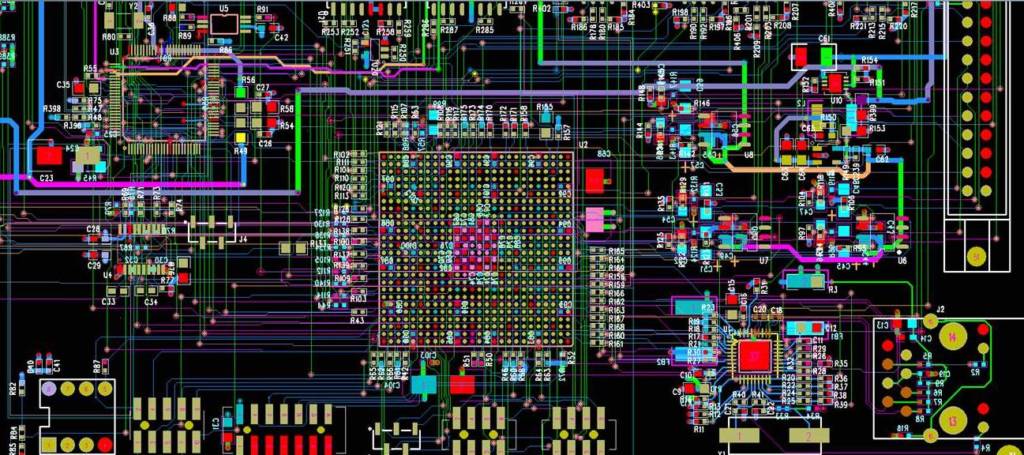
All printed circuit boards essentially perform similar functions, but there are three main types — rigid, rigid-flex, and flex — which all differ in terms of design and construction.
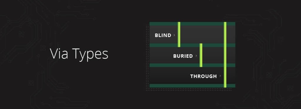
Vias are an essential part of the multi-layered printed circuit board (PCB) design and manufacturing process – but what are they exactly? And how do the various kinds differ from one another? In thi…